

Basic Electronic Components: Types, Working Principles & Applications
Guide to basic electronic components and functions: resistors, capacitors, diodes, transistors, and ICs with circuit diagrams and free PDF download.


Basic electronic components are the physical building blocks used to design, assemble, and troubleshoot electrical circuits. From passive elements like resistors, capacitors, and inductors to active semiconductor devices like diodes, transistors, and integrated circuits (ICs), every electronic gadget depends on these core parts to manage electric signals.
Whether you are designing embedded hardware, experimenting with IoT prototyping, or troubleshooting a breadboard circuit, understanding how each component functions from first principles is essential. In this detailed engineering guide, we break down active and passive components, their circuit symbols, formulas, color codes, and internal working mechanisms.
Before exploring each component, here is a quick visual introduction to the Basics of Electronic Components.
Printable Electronics Cheat Sheet: Component Quick Reference
Here is a 1-page summary cheat sheet of the core electronic components, their circuit symbols, standard SI units, governing formulas, and primary functions in hardware design:
| Component | Category | Circuit Symbol | Standard SI Unit | Governing Formula | Primary Circuit Function |
|---|---|---|---|---|---|
| Resistor | Passive | R (Zigzag / Box) | Ohm (Ω) | V = I × R | Limits current flow and drops voltage |
| Capacitor | Passive | C (Parallel Plates) | Farad (F) | Q = C × V | Stores electrostatic energy and filters ripples |
| Inductor | Passive | L (Wire Coil) | Henry (H) | V = L × (di/dt) | Stores magnetic energy and blocks AC noise |
| Diode | Active | Triangle to Bar | Volt (V) forward drop | Shockley Diode Eq. | One-way current valve and AC-to-DC rectification |
| BJT Transistor | Active | Base, Collector, Emitter | Current Gain (β) | Ic = β × Ib | Weak signal amplification and digital switching |
| MOSFET | Active | Gate, Drain, Source | Threshold Voltage (Vth) | Id ∝ (Vgs - Vth)² | High-speed power switching and logic gates |
| Light-Emitting Diode (LED) | Active | Diode with light arrows | Forward Voltage (Vf) | R = (Vs - Vf) / If | Emits photon light when forward biased |
| Integrated Circuit (IC) | Active | Multi-pin DIP / SMD package | Logic Truth Tables | Boolean Equations | Processing, timers (555), and microcontroller code |
Printable Lab Reference: To save this cheat sheet and complete guide for your workbench or offline study, press
Ctrl + P(Windows/Linux) orCmd + P(Mac) and choose Save as PDF. The page includes optimized print styles for clean, paper-saving output.
Active vs Passive Components: What is the Difference?
Every electronic component belongs to one of two main categories based on whether it can deliver net energy gain to a circuit: Active Components or Passive Components.
- Active Components: Components that can control electron flow, amplify weak electrical signals, or switch power. They require an external power source to operate. Examples include transistors, diodes, operational amplifiers, and integrated circuits.
- Passive Components: Components that cannot amplify or generate electrical energy. They store, filter, or dissipate energy without needing an external power supply. Examples include resistors, capacitors, and inductors.
Active vs Passive Components Comparison
| Feature | Active Components | Passive Components |
|---|---|---|
| External Power | Requires external DC voltage/current to operate | Operates entirely without external power |
| Power Gain | Capable of amplifying signal power (Gain > 1) | Cannot amplify power (Gain ≤ 1) |
| Signal Control | Dynamically controls and modulates current | Responds passively to applied voltage and current |
| Energy Role | Acts as an energy controller or donor | Absorbs, stores (electric/magnetic field), or dissipates energy |
| Key Examples | BJT, MOSFET, Diode, Op-Amp, Microcontrollers | Resistor, Capacitor, Inductor, Transformer |
| Typical Role | Switching, signal amplification, logic operations | Current limiting, timing, ripple filtering, impedance matching |
Basics of Resistors: Working Principles, Types & Color Codes
A resistor is a passive two-terminal electrical component that implements electrical resistance to limit the flow of electric current and lower voltage levels within a circuit according to Ohm's Law.

Think of resistors as speed breakers for electrons. Similar to how speed breakers encourage drivers to limit vehicle speed on roads, resistors restrict the flow of electric current to protect sensitive components like LEDs and microcontrollers.
Types of Resistors
There are two primary categories of resistors based on adjustability:
- Fixed Resistors:
The resistance value is set during manufacturing and cannot be adjusted. Common varieties include:
- Carbon Film Resistor: Economical, standard tolerance (±5%), widely used in general hobbyist circuits.
- Metal Film Resistor: High precision (±1%), low noise, superior temperature stability.
- Wirewound Resistor: Made by winding resistive wire around a ceramic core, built for high-power dissipation.
- Thick & Thin Film SMD Resistor: Surface-mount chips used in compact modern electronics.
- Variable Resistors:
The resistance can be adjusted manually or electronically. Examples include:
- Potentiometer: Three-terminal component used as a voltage divider (e.g., volume knobs).
- Rheostat: Two-terminal adjustable resistor used to control current.
- Trimpot (Preset): Miniature potentiometer calibrated once on a circuit board during production.
- Thermistor & LDR: Resistors whose resistance changes with temperature or ambient light.
Resistor Color Code Chart
Through-hole resistors use colored bands printed around their cylindrical bodies to represent resistance values and tolerances in accordance with the international EIA standard.
| Color | Significant Digit | Multiplier | Tolerance |
|---|---|---|---|
| Black | 0 | 1 Ω (10⁰) | - |
| Brown | 1 | 10 Ω (10¹) | ±1% |
| Red | 2 | 100 Ω (10²) | ±2% |
| Orange | 3 | 1 kΩ (10³) | - |
| Yellow | 4 | 10 kΩ (10⁴) | - |
| Green | 5 | 100 kΩ (10⁵) | ±0.5% |
| Blue | 6 | 1 MΩ (10⁶) | ±0.25% |
| Violet | 7 | 10 MΩ (10⁷) | ±0.1% |
| Grey | 8 | 100 MΩ (10⁸) | ±0.05% |
| White | 9 | 1 GΩ (10⁹) | - |
| Gold | - | 0.1 Ω (10⁻¹) | ±5% |
| Silver | - | 0.01 Ω (10⁻²) | ±10% |
For calculating 3 band resistor value:
1st band: it signifies 1st digit
2nd band: it signifies the 2nd digit
3rd band: this band signifies a multiplier
For calculating 4 band resistor value:
1st band: it signifies 1st digit
2nd band: it signifies the 2nd digit
3rd band: this band signifies a multiplier
4th band: this band signifies tolerance
For 5, 6 band resistors:
The last 2 bands have the same meaning but the first 3 or 4 bands are the significant digits in the case of 5 and 6-band resistors respectively
Example:

Here in this 5-band example:
- Bands 1, 2, and 3 represent significant digits: Yellow (4), Red (2), and Blue (6).
- Band 4 represents the multiplier: Orange (10³ or ×1,000).
- Band 5 represents the manufacturing tolerance: Silver (±10%).
Calculation:
426 × 1,000 Ω = 426,000 Ω = 426 kΩ ± 10%
💡 Interactive Tool: Calculate 3, 4, 5, or 6-band resistors instantly and decode SMD chip codes using our free Resistor Color Code Calculator. Features interactive 3D visual preview, reverse calculation (ohms to bands), and commercial E12/E24 nearest matches.
Key Mathematical Formulas for Resistors
- Ohm's Law: The fundamental relationship between voltage (V), current (I), and resistance (R):
V = I × R|I = V / R|R = V / I - Electric Power Dissipation: Electrical energy converted into heat by a resistor:
P = V × I = I² × R = V² / R(measured in Watts)
Practical Engineering Tip: Always verify the wattage rating of your resistors. Standard hobby through-hole resistors are rated for 1/4 Watt (0.25 W). If your circuit calculates
P > 0.25 W, use a 1/2 Watt or 1 Watt power resistor to prevent overheating and component failure.
Capacitors Explained: Working Principles & Types
A capacitor is a passive two-terminal electronic component that stores electrical energy electrostatically in an electric field created between two conducting plates separated by a dielectric insulating material.
When connected to a DC voltage source, electrons accumulate on one plate (creating a negative charge) while electrons leave the opposite plate (creating a positive charge). Even after disconnecting the voltage source, the electrostatic charge remains until discharged through a circuit path, allowing the capacitor to act like a temporary energy reservoir.
The ability of a capacitor to store charge is measured by its capacitance (C) in Farads (F):
C = Q / V
(where Q is the electric charge in Coulombs, and V is the voltage across the plates in Volts).
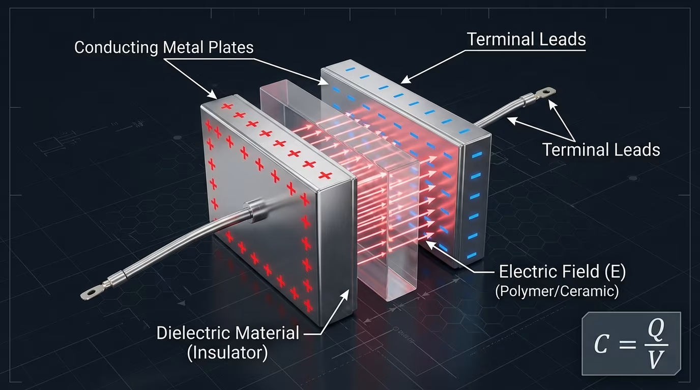
Types of capacitors
Following are the types of capacitors along with their dielectric material, capacitance, voltage ratings, and important characteristics.
Ceramic Capacitor
Dielectric Material: Ceramic
Capacitance: Typically ranges from picofarads (pF) to microfarads (uF).
Voltage Rating: Can range from a few volts to hundreds of volts.
Characteristics: Commonly used for high-frequency applications, compact size, and low cost.Electrolytic Capacitor:
Dielectric Material: Oxide layer
Capacitance: Higher values, often in microfarads (uF) to farads (F).
Voltage Rating: Usually for higher voltage applications.
Characteristics: Polarized (must be connected with the correct polarity), higher capacitance values, used for power supply filtering.Tantalum Capacitor:
Dielectric Material: Tantalum Oxide
Capacitance: Typically in the range of microfarads (uF) to farads (F).
Voltage Rating: Suitable for higher voltage applications.
Characteristics: Polarized, high stability, used in applications where reliability is critical.Film Capacitor:
Dielectric Material: Various types, including polyester (Mylar), polypropylene, and polyethylene.
Capacitance: Ranges from picofarads (pF) to microfarads (uF).
Voltage Rating: Varies, but can handle moderate voltage levels.
Characteristics: Non-polarized, good for precision applications, and available in various materials like polyester, polypropylene, and more.Variable Capacitor:
Dielectric Material: Conductive polymer
Capacitance: Adjustable, often used in tuning circuits.
Voltage Rating: Varies, typically low.
Characteristics: Designed to vary capacitance for tuning purposes in radios and other devices.Supercapacitor:
Dielectric Material: Electrochemical double layer.
Capacitance: Typically in the range of farads (F) or even hundreds of farads.
Voltage Rating: Can handle moderate voltages.
Characteristics: Known for high capacitance, rapid charge/discharge, and used in applications requiring quick energy storage and release.
Applications of Capacitors
Capacitors perform essential tasks in modern circuit design:
- Power Supply Smoothing: Filters ripple voltage in AC-to-DC power supplies, turning fluctuating rectified DC into smooth, steady DC.
- Decoupling / Bypass: Placed near digital ICs to suppress high-frequency voltage transients.
- Signal Coupling & DC Blocking: Passes alternating signals (AC) while blocking steady direct currents (DC).
- Resonant & Tuning Circuits: Paired with inductors in LC filters to tune specific radio frequencies.
- Motor Starting: Provides the initial phase shift required to start single-phase AC induction motors.
Engineering Tip: Breadboard Decoupling: When prototyping with microcontrollers like Arduino or ESP32, always place a 100 nF (0.1 µF) ceramic capacitor across VCC and GND as close to the chip as possible. This prevents sudden logic resets caused by switching noise.
Diodes: P-N Junction Operation & Types
A diode is a two-terminal semiconductor device that conducts electric current primarily in one direction (forward bias) while blocking current in the opposite direction (reverse bias) using a P-N junction.
A diode is formed by bonding a P-type semiconductor (doped with trivalent impurities to create abundant positive holes) with an N-type semiconductor (doped with pentavalent impurities to create free electrons).
At the junction interface, free electrons recombine with nearby holes, creating an insulating depletion region with an internal barrier potential:
- Forward Bias: When the Anode (+) is connected to positive voltage greater than the barrier potential (~0.7V for Silicon, ~0.3V for Germanium), the depletion layer collapses and current conducts freely.
- Reverse Bias: When the Cathode (-) is positive relative to the Anode, the depletion layer widens, blocking current flow except for a tiny leakage current.

Types and applications of diodes
There are various types of diodes, each designed for specific applications. Here's an overview of some common types of diodes:
- PN Junction Diode: The standard diode is composed of P-N semiconductor materials. Allows current to flow in one direction while blocking it in the other.
- Light Emitting Diode (LED): Emits light when current flows through it. Widely used in displays, indicators, and lighting applications.
- Zener Diode: Designed for voltage regulation and voltage reference applications. Provides a constant voltage across its terminals when operated in the reverse breakdown region.
- Schottky Diode: Known for its fast switching capabilities. Used in high-frequency and high-speed applications. Has a lower forward voltage drop compared to standard diodes.
- Varactor Diode (Varicap Diode): Used in tuning circuits, such as in radio receivers, to change the capacitance and tune specific frequencies.
- Avalanche Diode: Operates in the avalanche breakdown region. Used in avalanche photodiodes for detecting light.
Engineering Tip: Flyback Protection Diodes: When switching inductive loads like relays, solenoids, or DC motors with transistors, always place a diode (like 1N4007) in reverse-parallel across the coil. When the coil is switched off, the collapsing magnetic field creates a huge reverse voltage spike; the flyback diode safely recirculates this spike, preventing transistor destruction.
Transistors: Working Principles, BJT & MOSFET Basics
A transistor is a three-terminal semiconductor device used to amplify or switch electrical signals and power, operating by controlling current flow between two terminals using voltage or current applied to a third terminal.
Transistors are the foundational building blocks of all modern computing. Without them, integrated circuits and microprocessors would be impossible. In digital circuits, transistors act as ultra-fast switches representing binary 0s and 1s, switching millions or billions of times per second.
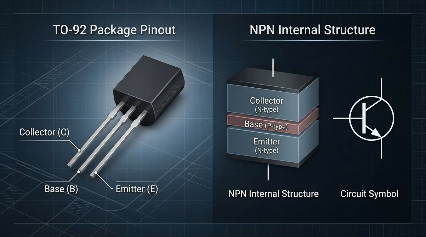
Here's an overview of transistors:
- Bipolar Junction Transistor (BJT): BJTs are three-layer semiconductor devices (N-P-N or P-N-P). They amplify current and can be used as switches. Commonly used in analog applications and amplifiers.
- Field-Effect Transistor (FET): FETs control current flow using an electric field. They are classified into MOSFETs (Metal-Oxide-Semiconductor FET) and JFETs (Junction FET). MOSFETs are commonly used in digital and power applications, while JFETs are used in low-frequency applications.
- MOSFET (Metal-Oxide-Semiconductor FET): MOSFETs are widely used in digital and power electronics. They have low power consumption, making them suitable for integrated circuits (ICs).
Key Functions and Significance:
- Amplification: Transistors amplify weak electrical signals, making them stronger. This is essential in audio amplifiers, radios, and other signal-processing applications.
- Switching: Transistors can act as electronic switches, controlling the flow of electrical current. In digital circuits, they enable us the represent binary logic i.e. 0s and 1s.
- Signal Modulation: Transistors also play a vital role in amplitude modulation (AM) and frequency modulation (FM) in communication systems.
- Voltage Regulation: They help regulate voltage levels in power supplies, ensuring stable and precise output voltages.
Engineering Tip: Transistor Base Resistors: When using a BJT as a microcontroller-driven switch, never connect a GPIO pin directly to the transistor Base. The Base-Emitter junction conducts like a forward-biased diode (~0.7V drop). A current-limiting base resistor (typically 1 kΩ to 10 kΩ) is required to protect both the microcontroller pin and the transistor.
Integrated Circuits (ICs) Overview
An Integrated Circuit (IC), also known as a microchip, is a monolithic assembly of electronic circuits containing thousands to billions of microscopic transistors, resistors, and capacitors fabricated onto a single semiconductor wafer (usually silicon).

Types of Integrated Circuits
- Analog ICs: Handle continuous signals for tasks like amplification and voltage regulation.
- Digital ICs: Process discrete binary signals (0s and 1s) for computing and memory functions.
- Mixed-Signal ICs: Combine analog and digital circuitry, used in devices like smartphones.
- RF ICs: Specialized for radio-frequency applications, like amplifying and processing wireless signals.
- Memory ICs: Store and retrieve data, from computer DRAM to flash memory in USB drives.
- Power Management ICs (PMICs): Regulate voltage and manage power in electronic devices.
- Communication ICs: Enable data transmission, including Ethernet controllers and wireless communication.
Microcontrollers in Embedded Systems & IoT
A microcontroller (MCU) is a compact integrated circuit designed to govern a specific operation in an embedded system, combining a processor core (CPU), memory (RAM and ROM/flash), and programmable input/output peripherals on a single silicon chip.

Common Microcontroller Platforms:
- 8051 Family: The classic 8-bit architecture developed by Intel, widely taught in engineering curricula for register-level programming. Learn more in our guide on Interfacing a 16x2 LCD with the 8051 Microcontroller.
- Arduino & ATmega328P: The standard open-source prototyping ecosystem. Explore our comprehensive Guide to Arduino Uno Boards, IDE & Programming.
- Wireless SoCs (ESP32, ESP8266 & Nordic): Modern 32-bit microcontrollers featuring integrated Wi-Fi and Bluetooth LE, powering modern IoT devices. See our troubleshooting breakdown for the ESP32 Packet Timeout Issue.
Quick Reference: Basic Electronic Components Summary Table
To help you quickly identify components while designing or debugging circuits, here is an at-a-glance cheat sheet:
| Component | Symbol / Unit | Type | Primary Function | Common Applications |
|---|---|---|---|---|
| Resistor | R (Ohms, Ω) | Passive | Restricts current flow, divides voltage | Current limiting for LEDs, pull-up/pull-down |
| Capacitor | C (Farads, F) | Passive | Stores electrostatic energy, filters noise | Power supply smoothing, timing circuits, decoupling |
| Inductor | L (Henries, H) | Passive | Stores energy in a magnetic field | Buck/Boost converters, RF chokes, low-pass filters |
| Diode | D (Volts drop, V) | Active / Semi | Allows one-way current flow | AC-to-DC rectification, flyback reverse protection |
| Transistor (BJT/MOSFET) | Q | Active | Amplifies signals, electronic switching | Motor driving, logic switching, audio amplifiers |
| Relay | K / RLY | Electromech | Electrically operated high-voltage switch | Home automation, AC mains control with microcontrollers |
| Microcontroller | MCU / U | Active (IC) | Executes programmed logic and firmware | Arduino UNO, IoT sensors, robotics |
Hands-On Projects Using These Components
Put this theoretical knowledge to use with practical hardware builds:
- Build a DIY Smoke Detector Alarm with Arduino & MQ-135: See resistors, buzzers, and gas sensors in action.
- Interfacing 16x2 LCD with Microcontrollers: Learn potentiometer contrast adjustment and digital bus wiring.
- Interfacing Dot Matrix Display with Arduino: Master multiplexed LED matrix driving.
- Top Electronics Project Ideas for Engineering Students: Browse curated project ideas spanning IoT, robotics, and sensors.
Free Bonus PDF Download
Thanks for reading this Article! As a token of our appreciation, download a free bonus PDF with Basic Electronic Components for Embedded Systems and IoT. Enjoy!
Conclusion and Future Insights
Whether you're a seasoned developer or a curious beginner, understanding the diverse range of electronic components and technologies is crucial for those who seek to innovate. From fundamental concepts like active components to the intricate workings of capacitors and diodes, the electronic landscape is vast and rich with possibilities. These basic electronic components are the building blocks of every electronic or electrical circuit.
As you embark into more advanced territories, the likes of transistors and integrated circuits (ICs) take center stage, enabling the incredible devices and systems we rely on daily. Each of these components and technologies plays a unique role, from amplifying signals to controlling power and even facilitating wireless communication.
It's within this intricate framework that microcontrollers find their place, offering the power to control, automate, and create. Whether you're exploring Arduino for creative projects or delving into the world of 8051 microcontrollers for practical applications, these tiny but mighty devices open the door to endless possibilities.
Ultimately, electronics is a journey that allows creators like me 😜 to bring their visions to life. With the right knowledge and tools, the possibilities are limitless, from designing smart homes to crafting interactive art installations. It's a world where curiosity and innovation unite to shape the technology of tomorrow.
So, whether you're a developer, a hobbyist, or a curious explorer, the electronic realm is yours to explore, experiment with, and innovate upon.
And that's a wrap on the basics of electronic components. In the future, we'll dive deeper into the fascinating world of electronic terminologies. Stay tuned for more electrifying insights. Signing off, Krypton.
Frequently Asked Questions
- What are the main types of electronic components?
Electronic components are broadly divided into two categories: active components (such as transistors, diodes, and ICs) that require external power to amplify or switch signals, and passive components (such as resistors, capacitors, and inductors) that operate without external power to store or dissipate energy.
- What are the fundamental components in electronics?
The fundamental building blocks are resistors, capacitors, inductors, diodes, transistors, and integrated circuits. Together, they regulate current, filter electrical signals, store electrostatic charge, and perform digital logic in circuits.
- How do resistors limit electric current in a circuit?
Resistors use less-conductive materials like carbon film or metal oxide to oppose the flow of free electrons. According to Ohm's Law (V = I * R), this creates a controlled voltage drop and limits the current passing through the branch.
- What is the primary role of a diode?
A diode acts as a one-way electronic valve. It allows electric current to flow freely when forward biased and blocks current when reverse biased, making it critical for AC-to-DC rectification and reverse polarity protection.
- What is the difference between active and passive components?
Active components can inject power gain into a signal and dynamically control electric current using an external supply. Passive components cannot amplify power and only absorb, store, or release electrical energy.
- What is a transistor used for in circuits?
A transistor acts as an electronic switch to turn current on or off, and as an amplifier to boost weak electrical signals. Transistors form the foundational switching units in audio amplifiers and modern computer processors.
- What is the purpose of a capacitor in electronics?
A capacitor stores electrical energy in an electrostatic field between conductive plates. It smooths voltage ripples in power supplies, filters high-frequency electrical noise, and passes AC signals while blocking steady DC.
- What is the difference between an integrated circuit and a microcontroller?
An integrated circuit (IC) is a miniature semiconductor chip housing interconnected transistors, resistors, and capacitors. A microcontroller is a specialized type of IC combining a CPU core, memory, and programmable I/O peripherals to execute dedicated firmware.
- What are the 10 basic electronic components?
The 10 most common basic electronic components are resistors, capacitors, inductors, diodes, light-emitting diodes (LEDs), bipolar junction transistors (BJTs), MOSFETs, transformers, relays, and integrated circuits (ICs).